How I Designed a Custom PEKK Implant
August 10, 2025
In the fall of 2024 I got the opportunity to join the Drexel Implant Research Center, working in collaboration with Thomas Jefferson University. The project was to develop a patient-specific design envelope for spinal implants made from a high-performance polymer called PEKK, aimed at patients with metastatic spinal lesions. I said yes immediately... maybe before I fully understood what I was signing up for.
The core problem is this: spinal implants that replace a damaged vertebra are traditionally made from titanium and come in standard sizes. But every spine is different. Different curvature, different vertebral height, different endplate geometry. An off-the-shelf implant is always a compromise. What we were building was a pipeline where you start with the patient's actual CT scan and end up with a device designed around their specific anatomy.
Why not just use titanium?
This was my first question too. Titanium is strong, biocompatible, and has decades of clinical history behind it. But there's a real catch. It's radiopaque, meaning it shows up as a bright white artifact on post-operative imaging, which means once it's implanted you can't clearly see what's happening at the fusion site. Is the bone integrating? Is something going wrong? You're partly flying blind.
PEKK is radiolucent, so nearly invisible on X-ray and CT, which means surgeons can actually monitor bone healing after surgery. It also has a stiffness closer to cortical bone, around 3 to 4 GPa. That matters because if your implant is dramatically stiffer than the surrounding bone, the bone stops bearing load and starts to atrophy over time. That's stress shielding, and it's one of the leading reasons implants loosen years down the line. And crucially for this project... PEKK can be 3D printed, which is what makes point-of-care fabrication actually feasible.
Step one: getting the geometry out of the scan
The first thing I had to do was take raw DICOM files, the image format CT scanners output, and turn them into a usable 3D model of the patient's vertebrae. I used Dicom to Print (D2P) and 3D Slicer to do this, in a process called segmentation: isolating the structure you care about from everything else in the scan.
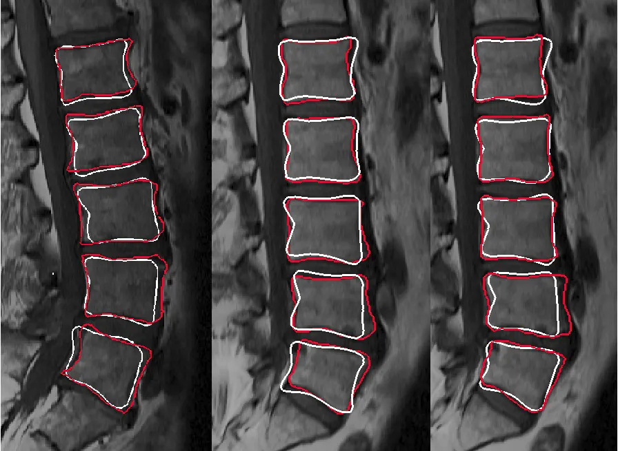
In theory, you set a threshold for bone density and the software highlights bone. In practice, the boundary between bone and soft tissue is never that clean. I ended up doing a lot of manual slice-by-slice correction, going through hundreds of 2D cross-sections and painting in or erasing pixels where the algorithm got it wrong. It is genuinely tedious work. I spent more time on segmentation than any other single step, and I came to understand why pretty fast. Bad geometry here means a poorly fitting implant downstream. You can't fix it later, so you fix it now.
The output is an STL mesh representing the patient's vertebral anatomy, and that mesh becomes the reference for everything that follows.
Designing the implant
With a clean mesh as a reference body, the actual implant design happened in CAD. We were developing a design envelope for cervical, thoracic, and lumbar regions, so not one implant but a range of boundary designs that could accommodate the anatomical variation across different patient cases.

There were a lot of constraints pulling in different directions at once. The implant has to match the endplate geometry of the vertebrae above and below it. It has to restore the correct disc height. It needs regions of internal porosity to allow bone ingrowth. And it has to actually be printable. Overhangs beyond about 45 degrees cause problems in FFF printing, and you obviously can't put support structures inside something going into someone's spine.
GD&T became really important here because we were designing for surgical fit. Too loose and the implant can migrate. Too tight and it can't be seated properly during the procedure. Getting those tolerances defined and testable is part of what separates this from just a CAD exercise. It's what makes the design regulatory-ready, aligned with FDA Design Control and ISO 13485 documentation practices.
What this taught me
The biggest thing was how truly interdisciplinary this work is. In a single week I might be doing image processing, parametric CAD, mechanical testing, and reading regulatory documentation. A gap in any one area shows up as a problem somewhere else, usually at the worst possible time.
Working directly with surgeons to define requirements also completely changed how I approach design. They'll tell you things about how an implant gets placed intraoperatively that you would never think of sitting at a workstation. That input is what closes the gap between something that works in a test fixture and something that works in an operating room. Two very different bars.
I wrapped up this project in early 2025 when I graduated, but it was one of the most technically demanding and rewarding things I worked on during my time at Drexel. If you're working on anything in the medical device or additive manufacturing space, feel free to reach out!