
Lessons from Collaborative Robotics
July 5, 2023
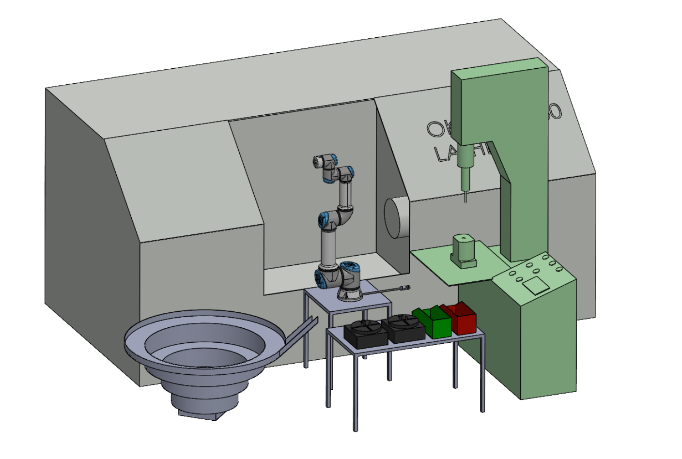
For our senior design project at Drexel, my team got paired with B&G Manufacturing, a machine shop that produces high-precision bolts on CNC lathes. Some of these bolts have tolerances down to .001 inches, and the entire process of running them through the Okuma LB15 lathe, a threading machine, and a diameter inspection station was completely manual. One operator, one bolt at a time, 9.4 minutes per part. The company wanted to automate it, but third-party solutions from companies like Fanuc and RAIS were quoting them anywhere from $100,000 to $250,000. Our goal was to build something equivalent for a fraction of that cost. We called the project CRIMMI.
The key constraint was that it had to work on an open floor alongside people. No safety cage. That's what made a collaborative robot the right choice here. A traditional industrial robot doesn't know you exist. A cobot, like the Universal Robots UR-20 we used, has force and torque sensing that shuts it down immediately on unexpected contact. Slower than an industrial robot, sure, but it could live right next to the machines without tearing up the floor plan.
The end-effector is the actual problem
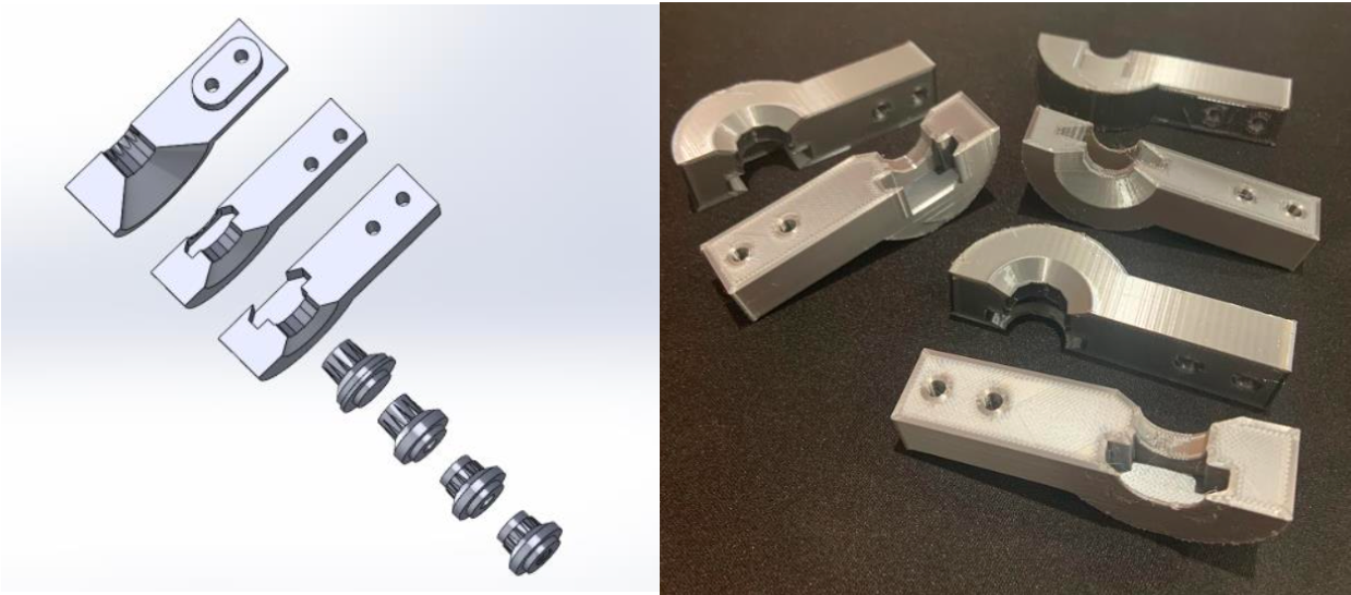
The UR-20 arm is a well-proven platform. You mount it, you program it, it does what you tell it. What nobody sells you off the shelf is a gripper designed for your specific bolt geometry, at your specific grip force, that can handle the bolt from two different angles, one to load into the lathe spindle from each side, and then again for the threader and inspection station. That's the engineering problem, and that's where we spent most of our time.
We modeled the end-effector in SolidWorks and went through three design versions before settling on something we were confident in. We used Prusa Slicer to prepare the files for 3D printing and tested each version physically. One thing that isn't obvious until you're doing it: the center of mass of the end-effector plus the bolt it's holding matters a lot. An offset center of mass creates a moment on the robot's wrist joint that shows up as positioning error over time. We caught that in CAD and fixed the geometry before we ever printed the final version, which saved a real headache.
What ANSYS caught that we missed
Before finalizing the end-effector, we ran FEA in ANSYS Workbench 2022 using a Quadratic Tetrahedron mesh with 5mm element size, refined at the semicircular grip regions where force is actually applied. That gave us 13,230 elements and 27,286 nodes to work with. We solved for equivalent Von Mises stress and total deformation across 18,830 cycles at a max force of 40N.
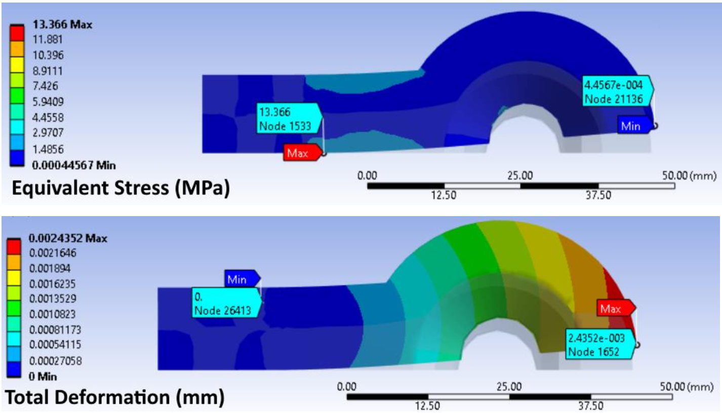
We tested both ABS and structural steel. ABS deflected 0.15196mm with an equivalent stress of 14.81 MPa. Steel came in at 0.00244mm deflection and 13.366 MPa stress. Not even close. We went with steel. It deforms far less over the life of the part, and when it does eventually wear out, it can be machined or reprinted in-house and swapped out quickly.
After the FEA, we ran an FMEA to walk through every failure mode we could think of. End-effector deforms over time and can't lift the bolt anymore? Robot can detect the deformation and flag it for replacement. Fracture at the connection point? Maximum stress over the 18,830 cycle lifespan stayed well below the material's fracture threshold, so this was low probability. Bolt too heavy for the gripper? Current bolts are under 1 oz, robot payload limit is 44 lbs. Not a concern. Doing the FMEA felt thorough at the time, and it ended up catching a few edge cases we hadn't thought of.
The results
The automated system brought cycle time down from 9.4 minutes to 5.5 minutes per bolt, a 41.51% improvement. A batch of 2,690 bolts that used to take 421 hours now takes around 246 hours. The total system cost came in at $74,406.93, which was under both our original $80,000 budget and under the salary of the worker the system was replacing. Payback period works out to about 1.2 years assuming 13 batches per year on an 8-hour shift. For B&G, that was well within what they needed to see to justify the investment.
The operator who had been running the machine manually didn't lose their job. They moved to higher-judgment work the robot can't do. That outcome mattered to me as much as the cycle time numbers, honestly.
What I'd tell someone starting a project like this
Talk to the operators before you finalize anything. We caught two failure modes we hadn't considered because someone on the floor told us how the parts actually behave in practice, as opposed to how they behave in a spec sheet. No simulation captures that knowledge. It's just in the room, if you ask.
Also, budget extra time for integration. Every individual piece of the system worked fine on its own. The first day we ran the full sequence end-to-end on the actual floor, several things did not work. That's normal, but plan for it. Integration is its own engineering problem and it will take longer than you think!