Building a Reflectivity Fixture from Scratch
March 28, 2021
During the winter of 2020 into 2021, I was interning at Horiba Instruments and I got handed a problem that sounded simple at first. The team needed a reliable way to measure the reflectivity of paint samples used on internal optical components. Basically, they needed to know exactly how much light a painted surface was absorbing versus bouncing back. The issue was that their current method was inconsistent. Different engineers would set the test up differently, get different results, and nobody was fully confident in the numbers. Every time they needed to test a new batch of paint, they were essentially starting from scratch.
They handed this to the intern. That intern was me. No pressure!
What even is a reflectivity fixture?
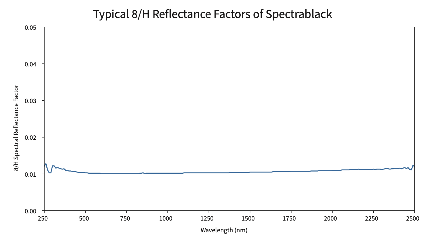
The goal was to design a physical fixture that would hold a paint sample at a precise angle and distance relative to the spectrometer's input optics, with a calibrated Spectralon black standard as the reference. Spectralon is a material with a very well-characterized reflectance across a wide wavelength range. It's basically the measurement baseline that everything else gets compared against.

The fixture needed to ensure that every time someone ran this test, the geometry was identical. Same sample position, same angle, same distance. That repeatability is the whole point. If the setup changes between tests, you can't compare results, and the data is meaningless.
Designing it
I modeled the fixture in SolidWorks, sourcing components from Thorlabs and McMaster-Carr where I could rather than fabricating everything from scratch. Thorlabs especially has a huge catalog of optical mounts and positioning hardware. If a component already exists with the precision you need, you use it. Designing it yourself takes time and you usually don't do it better than a company that specializes in it.

The tricky part was the alignment constraints. Optical measurements are sensitive to small angular errors in a way that mechanical assemblies often aren't. A few tenths of a degree off in sample tilt and your reflectance reading shifts meaningfully. I had to think carefully about how the fixture would actually be used in practice, because the most precisely designed fixture in the world doesn't help if a technician loading a sample can inadvertently knock the alignment out while doing it.
I iterated through a few design versions, each time running alignment tests to check repeatability and talking with the optical engineers to make sure the geometry matched what the spectrometer actually needed. They caught things I wouldn't have thought to check from a purely mechanical standpoint. That back and forth was genuinely useful and changed some of my design decisions.
The part I didn't expect
After I got the fixture working, I wrote up the testing procedure. How to load the sample, what settings to use, how to record the data, what to do if something looks off. Standard documentation. I figured it would sit in a folder somewhere.
While working through the procedure, I started looking into what external verification testing actually cost the team. If the fixture performed repeatably enough to replace those outside lab runs, the projected savings were around $10,000 a year. That wasn't the stated goal of the project, the goal was repeatability, but it was a concrete number that helped make the case for finishing it properly. My internship ended before the fixture moved past R&D, so I don't know whether it was ever adopted. But the prototype worked, the procedure was written, and the case for it was made.
What I learned
The biggest thing was learning to work at the intersection of mechanical and optical engineering. I came in thinking mostly mechanically... tolerances, fits, load paths. The optical engineers were thinking about wavefronts, alignment sensitivity, and measurement uncertainty. Getting fluent enough in their language to have productive conversations was a skill in itself, and honestly one of the most valuable things I took away from that internship.
I also learned that the scope of a project almost always expands once you're in it. What started as "design a fixture" turned into alignment testing, procedure writing, cross-team validation, and eventually a cost impact I hadn't anticipated. Going in with a clear idea of the deliverable but a willingness to follow where the problem actually leads you... that seems to be how useful engineering work actually happens.