Two Designs for a Spine Surgery Challenge
March 30, 2026
Globus Medical sent me a design challenge as part of their interview process. The brief was short: design an expandable height trial instrument for thoracolumbar corpectomy surgery. Requirements were collapsed height under 18mm, maximize expansion, handle a 50kg lift load, hand-operated only, approximately 150mm long, visible tip placement, and readable height display. That's it, the whole instruction set, with no other help, no hint at which direction to go.
I decided to design two completely different solutions from scratch and present them both. Here's how that went.
The clinical problem first
In a corpectomy, a damaged or diseased vertebral body gets removed entirely, usually because of either trauma or a metastatic tumor. That leaves a gap between the two adjacent healthy endplates. The surgeon needs to fill that gap with an implant, but every patient's gap is a different size. Wrong implant height means the spine isn't restored to the right geometry, and that creates biomechanical problems downstream.
A height trial solves this. You insert it collapsed so it fits through the gap, expand it until it fills the space and distracts the vertebral bodies apart, read the height, then choose the correctly sized permanent implant. It sounds simple but the dimensional constraints are pretty tight. The thoracic spine starts at vertebral body heights around 14.9mm at T1 and goes up to about 28mm at L5. The device has to fit into the smallest space and reach the largest, all while surviving 490.5 N of compressive load from body weight.
Design 1: the scissor jack approach
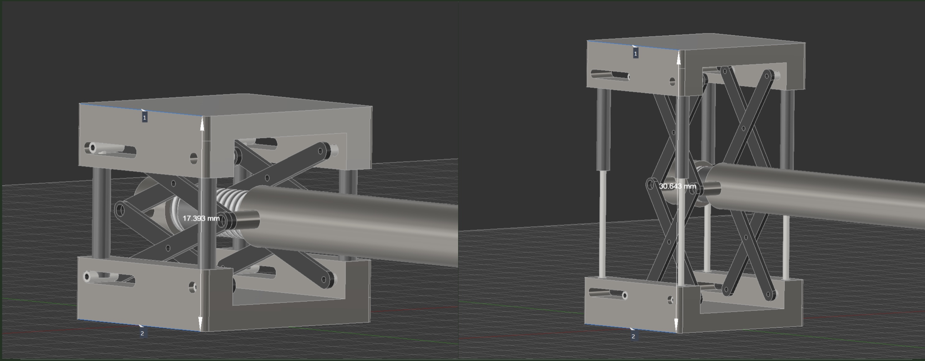
The first design uses a dual-layer scissor jack driven by a lead screw. The surgeon turns a handle which rotates the screw, the screw drives the scissor assemblies horizontally inward, and that horizontal compression forces the jaw plates apart vertically. Classic scissor jack geometry, miniaturized to fit inside a 17.393mm collapsed height.
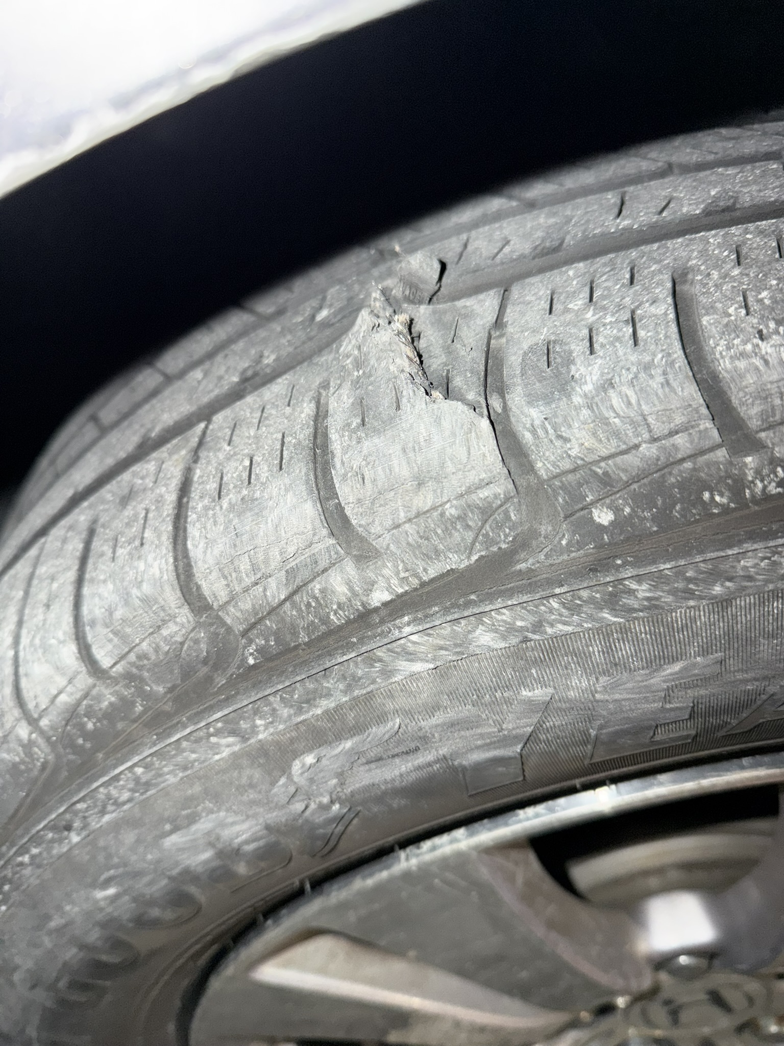
Funnily enough my inspiration for this actually came to me when one of the tires on my wheels exploded as I was driving down the highway and I had to put my spare on. As I was using that car jack to lift the car up, it hit me that I was looking at exactly what I needed for this challenge. A scissor jack! Obviously its one of the best compact mechanical systems for lifting heavy loads vertically. Duh! That same night I sat down and started figuring out how to model a novel scissor jack mechanism in fusion 360 that would match the challenge parameters.
The interesting part was working out the force chain using virtual work. The principle is simple: in a frictionless rigid linkage, input work equals output work. What I found was that at the starting position, the geometric ratio between vertical jaw displacement and horizontal screw displacement was 4.625. That means for every 1mm the scissors close horizontally, the jaw moves 4.625mm vertically. By force-velocity duality, that same ratio applies in reverse to forces. The lead screw needs to generate 4.625 times the required distraction force.
So instead of the screw needing to produce 490.5 N... it needs to produce 2,268.5 N. That was a sobering number to write down. But it's not an error in the design, it's a geometric consequence that you document and account for. The good news is that the lead screw handles it easily, and the mechanical advantage actually improves as the scissor opens further, so the worst case is always right at the starting position.
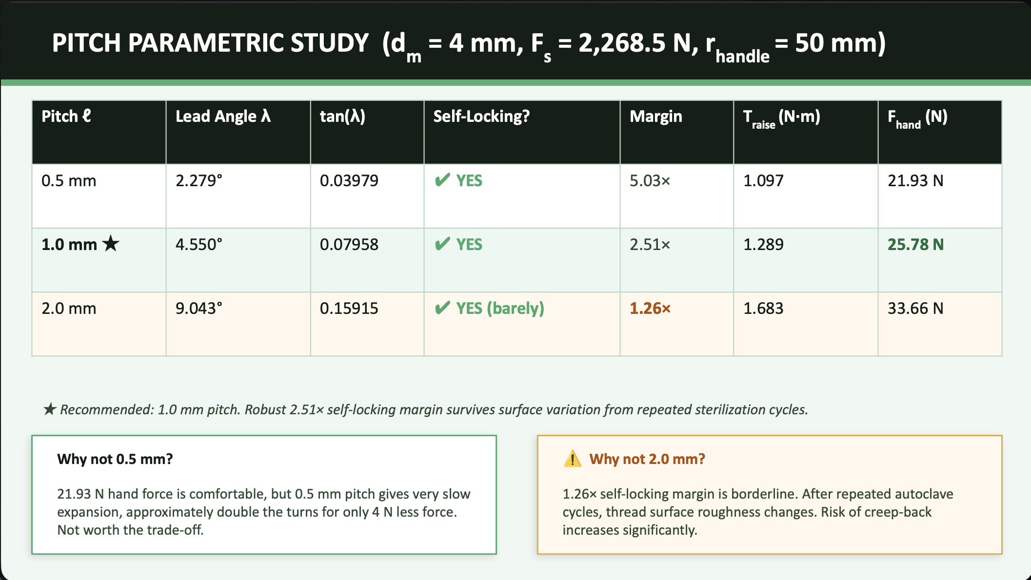
For the lead screw itself I ran a parametric study on pitch selection, which turned out to be more consequential than I expected. At 1.0mm pitch the self-locking margin is 2.51x, meaning the thread friction is 2.51 times what would be needed for the screw to back-drive under load. That's the right choice. At 2.0mm pitch the margin drops to 1.26x, which sounds okay until you think about repeated autoclave sterilization cycles changing the surface roughness of the stainless steel threads. That 1.26x margin could drift below the threshold. Not a risk worth taking in a surgical instrument.
The height readout for Design 1 is a laser-etched millimeter scale on the lead screw shaft that moves past a stationary collar on the body of the instrument. Exactly like reading a micrometer. One important detail: the scale markings are NOT uniformly spaced. The relationship between screw rotation and jaw height is nonlinear due to the scissor geometry, so each millimeter mark has to be placed at the screw position that corresponds to that actual jaw height from the kinematic model. A uniform scale would give wrong readings. The engravings go 0.15mm deep into the steel so they survive any sterilization process without fading.
Design 2: Pascal's Law does the lifting
The second design came from asking a different question: what if there were no mechanical linkage in the head at all? The answer was hydraulics.
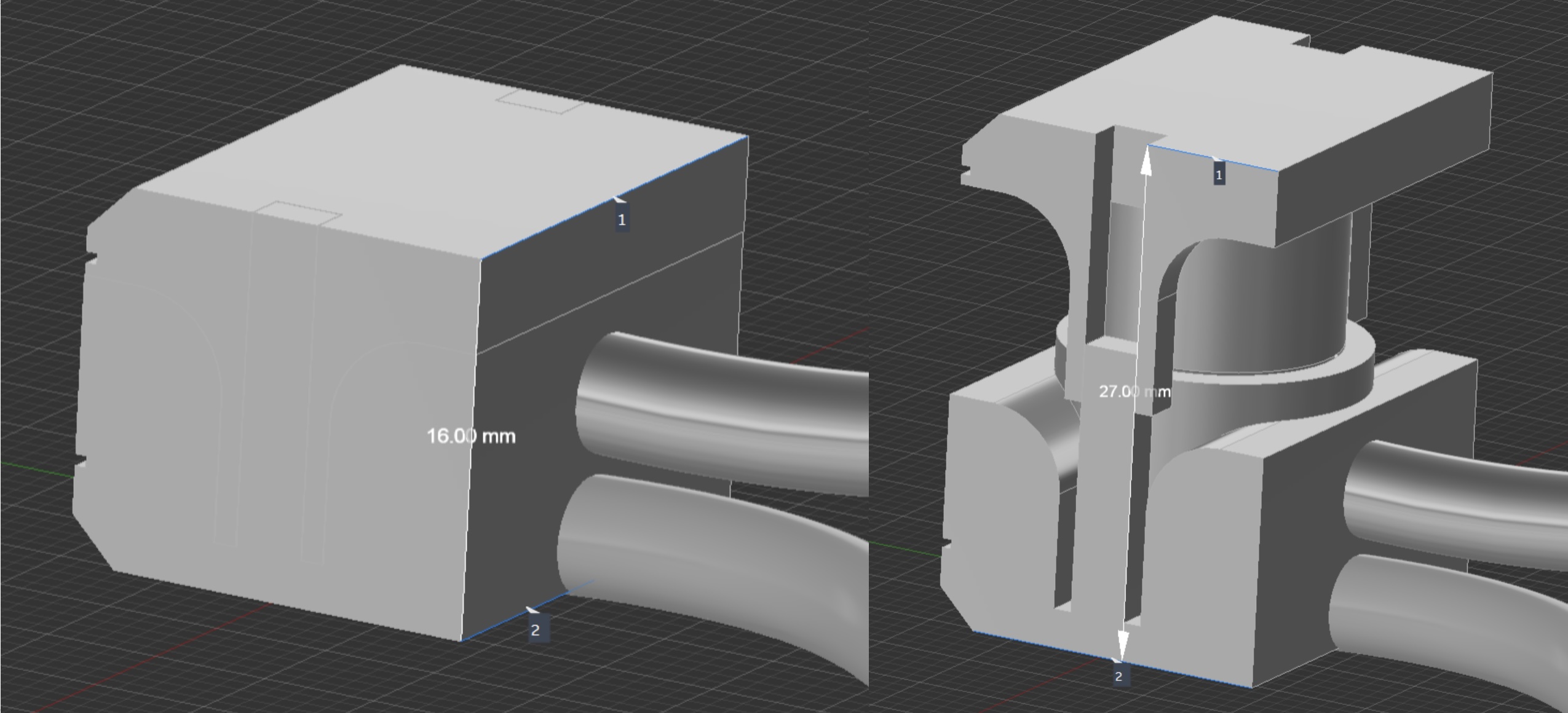
The inferior jaw plate is machined as a hydraulic cylinder. The superior jaw plate is the piston. A lead screw in the handle drives a small master piston that pumps sterile saline through a 2mm bore channel in the shaft, pressurizing the slave cylinder at the tip. Pascal's Law handles the rest: pressure is equal throughout an incompressible fluid, so if the slave piston area is larger than the master piston area, the slave generates proportionally more force. With a 13mm slave and 8mm master, a 6.68 N thumb force on the handle produces 490.5 N of distraction force at the tip.
The problem I ran into was the volume math. To travel 11mm, the 13mm slave piston needs to displace 1.460 mL of fluid. If you tried to push that in a single stroke of the master piston, an 8mm master would need a 29mm plunger stroke, which barely fits the handle. A smaller master piston makes the stroke even longer and the geometry completely impossible. Force and stroke fight each other, and with a single stroke you can't win both.
The solution was to break the total stroke into small steps using the same lead screw and thumb wheel approach. Each full revolution of the thumb wheel advances the master plunger 1.0mm, displacing enough fluid to move the slave piston 0.379mm. Full 11mm travel takes 29 turns, which takes about 3 to 5 seconds. The lead screw is self-locking with a 2.4x margin, so hydraulic back-pressure can't reverse the thumb wheel. Height holds passively.
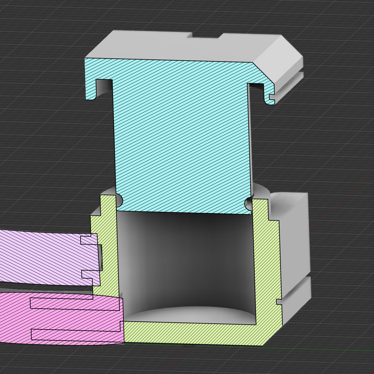
For the wall thickness of the slave cylinder I originally used thin-wall hoop stress assumptions. When I went back and checked the geometry, the wall-to-radius ratio came out to 0.308, which exceeds the 0.1 threshold where thin-wall assumptions are valid. Correcting it with the proper Lame thick-wall equations changed the maximum hoop stress from 12.0 MPa to 14.11 MPa, and the safety factor from 91.6 to 77.9. The wall is still sound, the safety factor is still enormous, but the formula and the stated values in the presentation needed updating. That's the kind of thing you catch when you check your assumptions, not just your arithmetic.
Design 2's height readout is actually a dual system. Primary is the exposed piston length above the cylinder rim, which directly equals the expansion above the 14mm baseline. No conversion needed, just read what's visible. Secondary is the same etched lead screw plus barrel collar approach from Design 1, giving a second independent confirmation of the reading at the handle end.
Comparing them honestly
Design 1 covers a wider range, 17.393 to 30.643mm, which spans the full thoracolumbar spectrum. It's all metal with no seals, which makes sterilization simple and removes one potential failure mode. The weakness is the geometric force disadvantage at the starting position and the tight 0.607mm margin below the 18mm constraint.
Design 2 requires about 4N less thumb force, has no moving parts in the head, and delivers more uniform endplate force distribution which matters particularly in osteoporotic bone. The weakness is the O-ring, which is a single point of failure that demands tight bore tolerances and a validated cleaning protocol if the device is reusable. It also needs to be primed with saline and air-bled before each use, which adds a step to the surgical workflow.
Neither design is strictly better. The choice depends on the clinical context, the surgeon's preference, and what sterilization infrastructure the hospital has. I presented both to the Globus interview board with that conclusion, because I think arriving at "it depends, and here's exactly what it depends on" is more useful than forcing a single answer when the tradeoffs are genuinely context-dependent.
What I took away from this
Running two parallel designs forced a level of rigor I wouldn't have applied to just one. When you have a second approach, every assumption in the first one gets questioned. Why a scissor jack? What does hydraulics give you that mechanical linkages don't? Answering those questions for yourself before someone in an interview room asks them is the whole game.
The other thing this project reinforced is that catching your own errors matters more than not making them. The thin-wall pressure vessel assumption was wrong, and I found it by going back and checking the geometry against the validity conditions for the formula. The result still shows a safe design, but the stated values were incorrect. Documenting that correction honestly is better than leaving wrong numbers in a polished slide deck and hoping nobody notices.